
The patent for the 6502’s ALU adder circuits, now expired, I found while writing a BCD adder in Verilog to go with a toy 6502ish CPU I am designing. So, I thought I’d re-implement it loosely based on the MOS solution.
The following schematic is unlikely to be needed, but might shed some light on the details. The scans have been pasted together, but don’t quite align towards the bottom. Some squinting will be required to make sense of it. There are a few lines that look unconnected, which I assume are just separators.
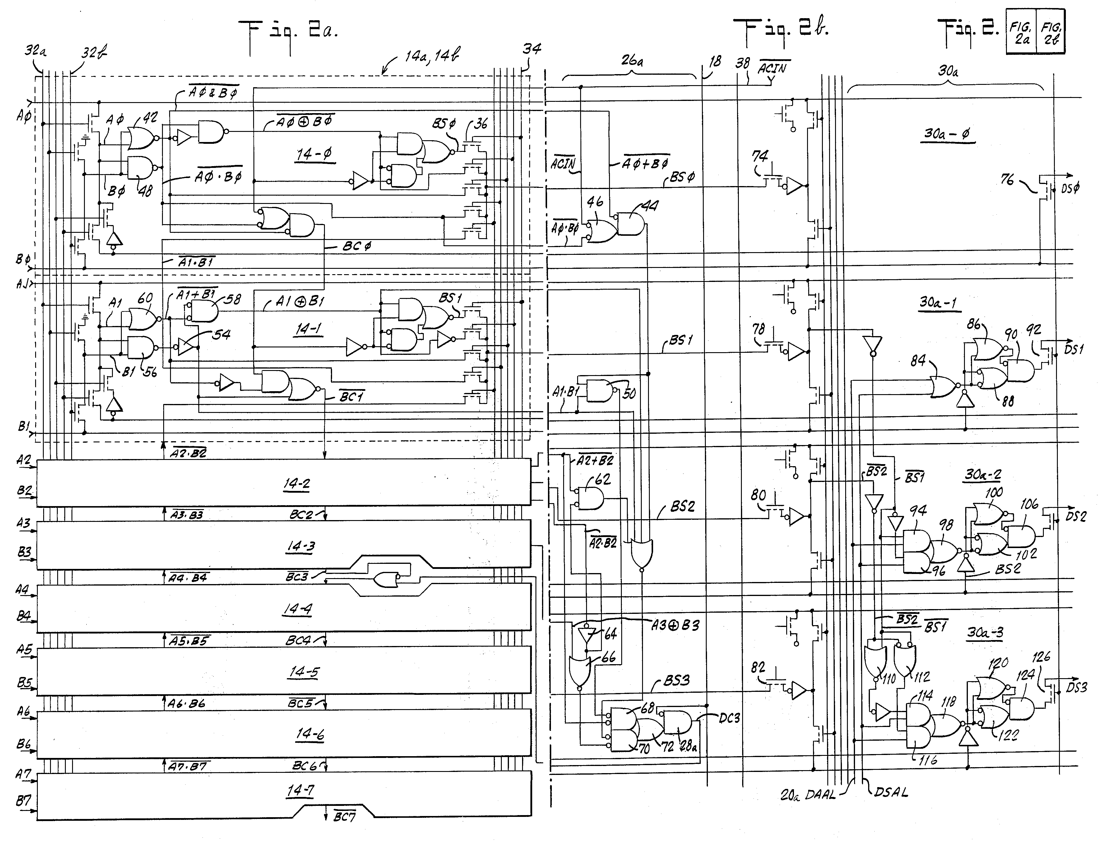
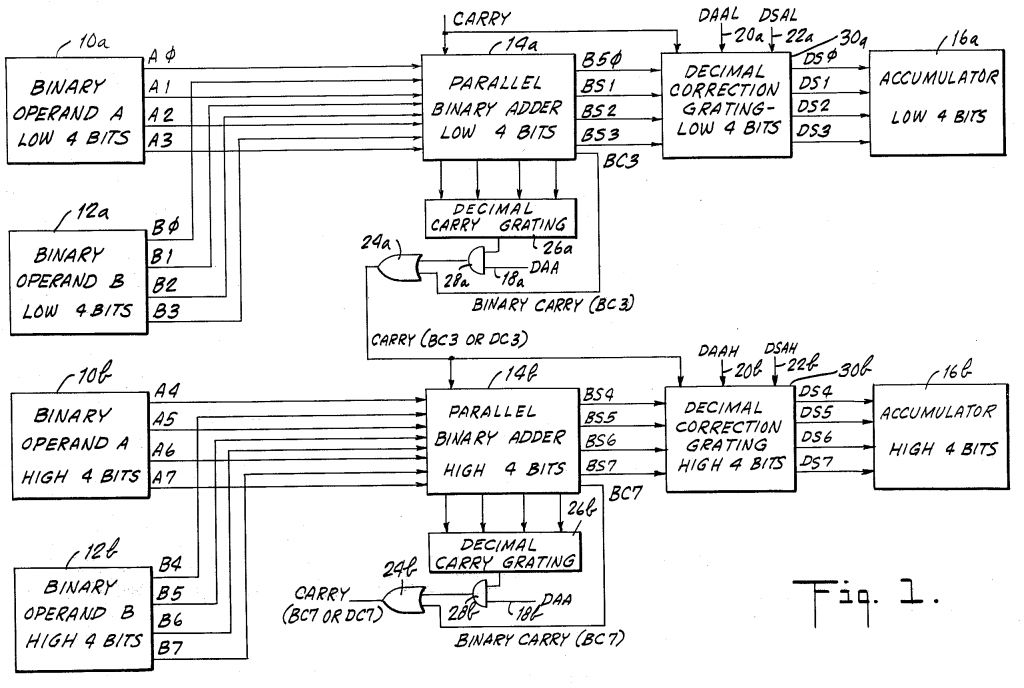
Roughly, the schematic is formed by three columns, the left side defines the binary adder, the middle shows the decimal carry calculation, and the right side generates the decimal correction.
The patent text really just describes the gates implemented above. However, it talks about them logically, rather than referring to the actual gates used, so unless you can apply De Morgan’s’ laws as you read (I can’t!), then it will be slow going trying to figure it all out.
The C code below is a behavioural implementation of the circuits described in the patent. It doesn’t overlap exactly the diagram in Fig.1, e.g. the carry flags are generated in the adder module rather than being derived separately using gates.
The code in the main() block generates test data output for the adder, the decimal corrector, and then both parts combined into two 4-bit adders.
#include <stdio.h>
#include <stdbool.h>

/*
 * The Parallel Binary Adder - (4-bit) module.
 */
void pbAdder(
        unsigned char A,        // 4-bit nibble
        unsigned char B,        // 4-bit nibble
        bool Cin,               // Carry in
        unsigned char *BS,      // Binary Sum
        bool *BC,               // Binary Carry
        bool *DC)               // Decimal Carry
{
        // Sanitise 8-bit values to 4 bits.
        A = A & 0xf;
        B = B & 0xf;

        *BS = (A + B + Cin) & 0xf;
        *BC = ((A + B + Cin) & 0x10) != 0;
        *DC = (A + B + Cin) > 9;

        printf("A=%d, B=%d, BS=%d, BC=%d, DC=%d\n", A, B, *BS, *BC, *DC);
}

/*
 * Decimal correction gating, generating DS (final ACC output)
 */
void dcGating(
        unsigned char BS,       // 4-bit Binary Sum
        bool DAA,               // Decimal Addition flag
        bool DSA,               // Decimal Subtraction flag
        unsigned char *DS)      // Decimal Sum (or Binary pass-thru)
{
        bool BS0 = (BS & 1);
        bool BS1 = (BS & 2) >> 1;
        bool BS2 = (BS & 4) >> 2;
        bool BS3 = (BS & 8) >> 3;

        bool DS0 = BS0;
        bool DS1 = (DAA | DSA) ^ BS1;
        bool DS2 = ((DSA & BS1) | (DAA & ~BS1)) ^ BS2;
        bool DS3 = ( ((BS1 | BS2) & DAA) | (~BS1 | ~BS2) & DSA) ^ BS3;

        printf("BS: %d%d%d%d\t", BS3, BS2, BS1, BS0);
        printf("DS: %d%d%d%d\n", DS3, DS2, DS1, DS0);

        // Select DS if resulting decimal is 0xa thru 0xf
        *DS = (DAA | DSA) & BS3 & (BS1|BS2)
                ? DS3 << 3|DS2 << 2|DS1 << 1 | DS0
                : BS3 << 3|BS2 << 2|BS1 << 1 | BS0;
        printf("ACC OUT: %02X\n", *DS);
}

void main()
{
        // Test some 4-bit addition and carry outputs.
        unsigned char sum;
        bool BC3;       // Binary Carry from adder bit 3
        bool DC3;       // Decimal Carry from adder bit 3

        // Test data 1 - mostly boundary cases. {A, B, Cin}
        unsigned char td1[][3] = { {1,2,0}, {8,1,0}, {8,1,1},
                {9,1,0}, {9,1,1}, {14,1,0}, {14,1,1} };
        int num_td1 = sizeof(td1) / sizeof(*td1);

        int i;
        for(i=0; i < num_td1; i++) {
                pbAdder(td1[i][0], td1[i][1], td1[i][2],
                        &sum, &BC3, &DC3);
        }

        // Enumerate all adder outputs, with decimal corrections.
        unsigned char accumulator;

        for(i=9; i < 16; i++) {
                printf("\n");

                dcGating(i, 1, 0, &accumulator);
        }
        printf("\n");

        // Test combination of two 4-bit adders

        unsigned char td2[][5] = {
                {0, 15, 0, 0, 0},
                {240, 15, 0, 0, 0},
                {0x98, 1, 0, 1, 0},
                {0x98, 1, 1, 1, 0},
                {0x98, 2, 0, 1, 0},
                {0x99, ~2, 1, 0, 1},
                {0x99, ~0x22, 1, 0, 1},
                {100, ~2, 1, 0, 0}
        };
        int num_td2 = sizeof(td2) / sizeof(*td2);

        for(i=0; i < num_td2; i++) {

                unsigned char A=td2[i][0], B=td2[i][1];
                bool Cin = td2[i][2];
                bool DAA=td2[i][3], DSA=td2[i][4];
                unsigned char sumL, sumH;
                unsigned char ACC;

                printf("A:%02X (%d), B:%02X (%d), Cin:%d\n",
                        A, A, B, B, Cin);

                pbAdder(A&0xf, B&0xf, Cin, &sumL, &BC3, &DC3);
                dcGating(sumL, DAA, DSA, &sumL);
                pbAdder((A&0xf0)>>4, (B&0xf0)>>4, DAA&DC3|BC3,
                        &sumH, &BC3, &DC3);
                dcGating(sumH, DAA, DSA, &sumH);

                ACC=sumH * 16 + sumL;
                printf("8-Bit OUT: 0x%02X (%d) BC=%d, DC=%d\n\n",
                        ACC, ACC, BC3, DC3);
        }
}
A:00 (0), B:0F (15), Cin:0
A=0, B=15, BS=15, BC=0, DC=1
BS: 1111        DS: 1111
ACC OUT: 0F
A=0, B=0, BS=0, BC=0, DC=0
BS: 0000        DS: 0000
ACC OUT: 00
8-Bit OUT: 0x0F (15) BC=0, DC=0

A:F0 (240), B:0F (15), Cin:0
A=0, B=15, BS=15, BC=0, DC=1
BS: 1111        DS: 1111
ACC OUT: 0F
A=15, B=0, BS=15, BC=0, DC=1
BS: 1111        DS: 1111
ACC OUT: 0F
8-Bit OUT: 0xFF (255) BC=0, DC=1

A:98 (152), B:01 (1), Cin:0
A=8, B=1, BS=9, BC=0, DC=0
BS: 1001        DS: 1111
ACC OUT: 09
A=9, B=0, BS=9, BC=0, DC=0
BS: 1001        DS: 1111
ACC OUT: 09
8-Bit OUT: 0x99 (153) BC=0, DC=0

A:98 (152), B:01 (1), Cin:1
A=8, B=1, BS=10, BC=0, DC=1
BS: 1010        DS: 0000
ACC OUT: 00
A=9, B=0, BS=10, BC=0, DC=1
BS: 1010        DS: 0000
ACC OUT: 00
8-Bit OUT: 0x00 (0) BC=0, DC=1

A:98 (152), B:02 (2), Cin:0
A=8, B=2, BS=10, BC=0, DC=1
BS: 1010        DS: 0000
ACC OUT: 00
A=9, B=0, BS=10, BC=0, DC=1
BS: 1010        DS: 0000
ACC OUT: 00
8-Bit OUT: 0x00 (0) BC=0, DC=1

A:99 (153), B:FD (253), Cin:1
A=9, B=13, BS=7, BC=1, DC=1
BS: 0111        DS: 0001
ACC OUT: 07
A=9, B=15, BS=9, BC=1, DC=1
BS: 1001        DS: 0011
ACC OUT: 09
8-Bit OUT: 0x97 (151) BC=1, DC=1

A:99 (153), B:DD (221), Cin:1
A=9, B=13, BS=7, BC=1, DC=1
BS: 0111        DS: 0001
ACC OUT: 07
A=9, B=13, BS=7, BC=1, DC=1
BS: 0111        DS: 0001
ACC OUT: 07
8-Bit OUT: 0x77 (119) BC=1, DC=1

A:64 (100), B:FD (253), Cin:1
A=4, B=13, BS=2, BC=1, DC=1
BS: 0010        DS: 0010
ACC OUT: 02
A=6, B=15, BS=6, BC=1, DC=1
BS: 0110        DS: 0110
ACC OUT: 06
8-Bit OUT: 0x62 (98) BC=1, DC=1
The output from the 8-bit operations is shown in the right-hand column. Note that the patent is based on the NMOS version of the 6502, and predates the CMOS version that included changes to the way flags get handled.
The test data provides negative numbers pre-converted to 2’s complement form, which would normally be done within the ALU.
This code was written as an intermediate step to be subsequently converted to Verilog – I’m more familiar with C, so this made sense to me. A hardware engineer would doubtless go straight to the testbench.
The Verilog code below behaviourally describes the 4 bit adder. The carry input to the next 4-bit adder is Cdec (decimal carry), though in the full implementation this would be DAA & Cdec | Cbin (decimal flag AND decimal carry, or binary carry).
/*
 * BCD Digit Adder
 * Given two 4 bit inputs and a carry, produce a BCD addition.
 */

module bcdAdder(
  input DSA,
  input [3:0] A,
  input [3:0] B,
  input Cin,
  output [3:0] OUT,
  output Cbin,
  output Cdec
);

wire [4:0] binSum;

assign binSum = (A + B) + Cin;
assign OUT = (binSum[3:0] > 9) ? (DSA ? (binSum - 6)&15 : binSum + 6) : binSum;
assign Cbin = binSum[4];
assign Cdec = (binSum > 9) ^ DSA;

endmodule
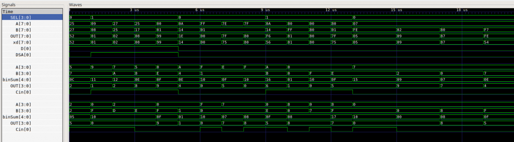
Here’s the code that puts two of these together to form an 8-bit BCD parallel adder inside the ALU. I have a testbed to generate some signals to show typical and boundary calculations, with the results shown in the GTKWave traces below.
/*
 * A 6502-like ALU.
 */
module alu(
  input [7:0] A,
  input [7:0] B,
  input Cin,
  input D,
  input [3:0] SEL,
  output [7:0] OUT,
  output C,
  output Z,
  output V,
  output N
);

`include "alu_params.h"

reg [8:0] x;

// BCD adder wires
wire [7:0] xd;
wire Cbin, hCbin;
wire Cdec, hCdec;

wire sub = (SEL == op_sub);

assign OUT = D ? xd : x[7:0];
assign C = (sub ^ x[8]);
assign N = x[7];
assign V = ( (A[7] ^ x[7]) & ((sub ^ B[7]) ^ x[7]) ) != 0;
assign Z = (OUT == 0);

always @(A, B, Cin, D, SEL)
  begin
    case(SEL)
    op_add : x <= (A + B) + Cin;
    op_sub : x <= (A + (~B)) + Cin;
    op_and : x <= (A & B);
    op_or  : x <= (A | B);
    op_xor : x <= (A ^ B);
    op_asl : x <= (A << 1);
    op_asr : x <= (A >> 1);
    op_lsl : x <= (A << 1);
    op_lsr : x <= (A >> 1);
    endcase
  end

bcdAdder bcdd1(D & (SEL == op_sub),
  A[3:0], SEL == op_sub ? ~B[3:0] : B[3:0], Cin, xd[3:0], hCbin, hCdec
);
bcdAdder bcdd2(D & (SEL == op_sub),
  A[7:4], SEL==op_sub?~B[7:4]:B[7:4], (D & hCdec)|hCbin, xd[7:4], Cbin, Cdec
);

endmodule

/*
 * BCD Digit Adder
 * Given two 4 bit inputs and a carry, produce a BCD addition.
 */

module bcdAdder(
  input DSA,
  input [3:0] A,
  input [3:0] B,
  input Cin,
  output [3:0] OUT,
  output Cbin,
  output Cdec
);

wire [4:0] binSum;

assign binSum = (A + B) + Cin;
assign OUT = (binSum[3:0] > 9) ? (DSA ? (binSum - 6)&15 : binSum + 6) : binSum;
assign Cbin = binSum[4];
assign Cdec = (binSum > 9) ^ DSA;

endmodule
The resulting waveforms are shown below, which includes both the nibble adders as well as the register inputs and outputs.
So, that’s good enough for now, though it feels a bit messy; I have a strong suspicion that there’s redundancy in my implementation, but until I evaluate the gates in the schematic and implement it more accurately, it’s not pressing enough for me to bottom out. I’ll revisit when I have a bit more Verilog under my belt.